3D Lattice Structure Design for Additive Manufacturing

In my article about „Creating basic lattice structures with Blender 3D“ , I already mentioned the huge advantages of lattice designs for additive manufacturing and showed you the Wireframe Modifier feature of Blender 3D . In this article I will show you one approach to create 3D lattice structures, not just on the surface but also creating lattice structures in the 3D volume of your designs. This way you can create stiff volumes with drastically less weight and production costs. By using the Weight Paint mode, you can adapt completely freely the lattice thickness of your designs.

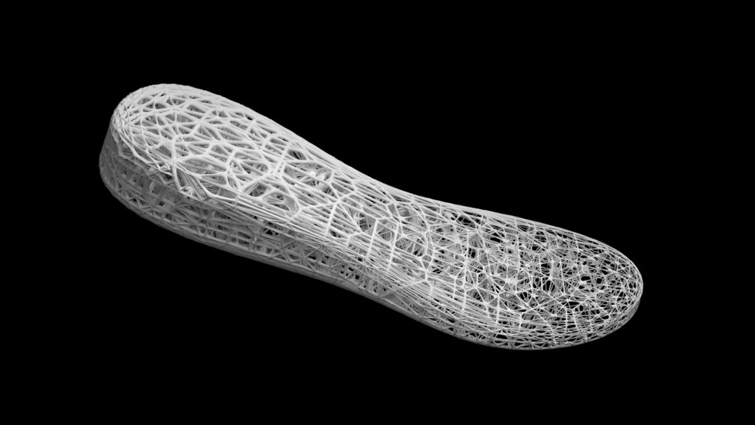
The application I am showing in the video, is a shoe sole with a lattice thickness adapted to the desired stiffness and flexibility at the different areas of the sole.

Creating 3D Lattice Structure designs for Additive Manufacturing

3D Design for Lattice Structure

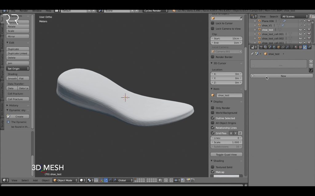
First of all you need a 3D mesh or an STL file to define the form of your resulting lattice structure. In the video I’m using the shape of a shoe sole.

If your mesh is of a very high resolution, you should use the Decimate Modifier to reduce the mesh size. The mesh size is ideally the size of the holes you would like to have in your lattice structure.

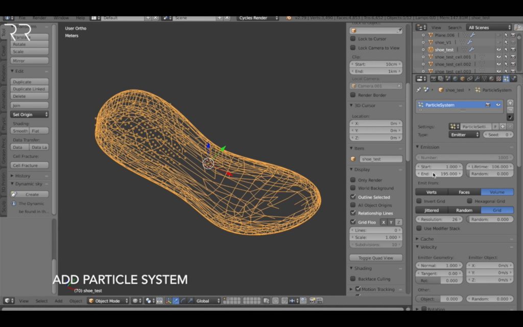
1. Create Particle System

In this approach I’m using the particles of the Particle System to define the connection points of the final lattice structure. You can chose different particle systems, like random and hair to create your particles. I see the volume and grid setting as the most homogenous approach, to have a feeling about the connection points inside the volume of the printed part.

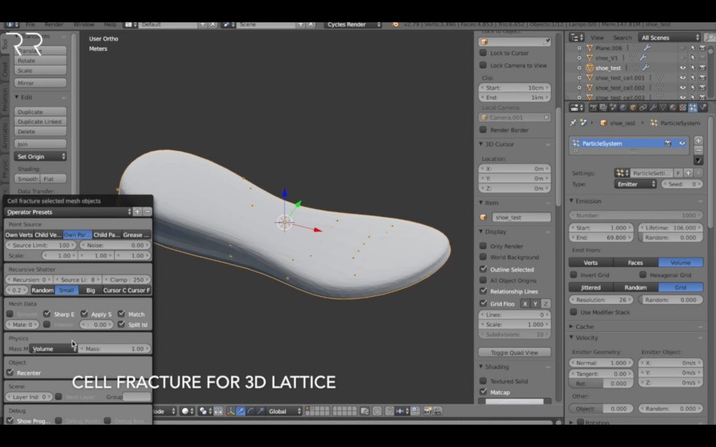
2. Use Cell Fracture Tool for 3D Lattice

The Cell Fracture tool breaks your mesh apart into small shatters with connection points at the previously defined particle locations. You can use different settings to create different fracture images and also a recursive fracture. You will probably have to turn on this tool under Blender Preferences Addons .

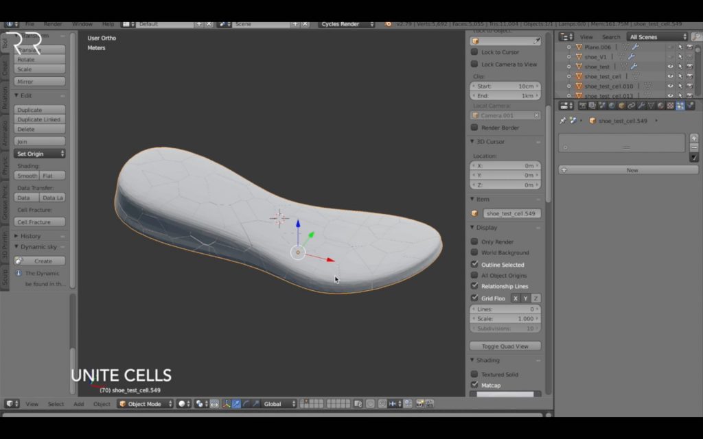
3. Unite Fractured Cells

Since the fracture tool creates independent cells, you have to select all, chose one as active object and combine them to one object with Ctr-J. Afterwards you can apply one modifier to the whole part.

4. Wireframe Modifier for Lattice Connections

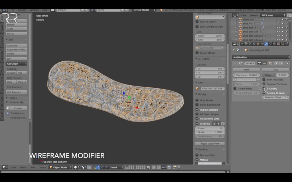
After creating a new 3D mesh with edges inside, we can apply the Wireframe Modifier to create a lattice structure on the newly created mesh. You can adapt the thickness of the lattice and ideally uncheck even thickness to avoid errors.

5. Create Vertex Group

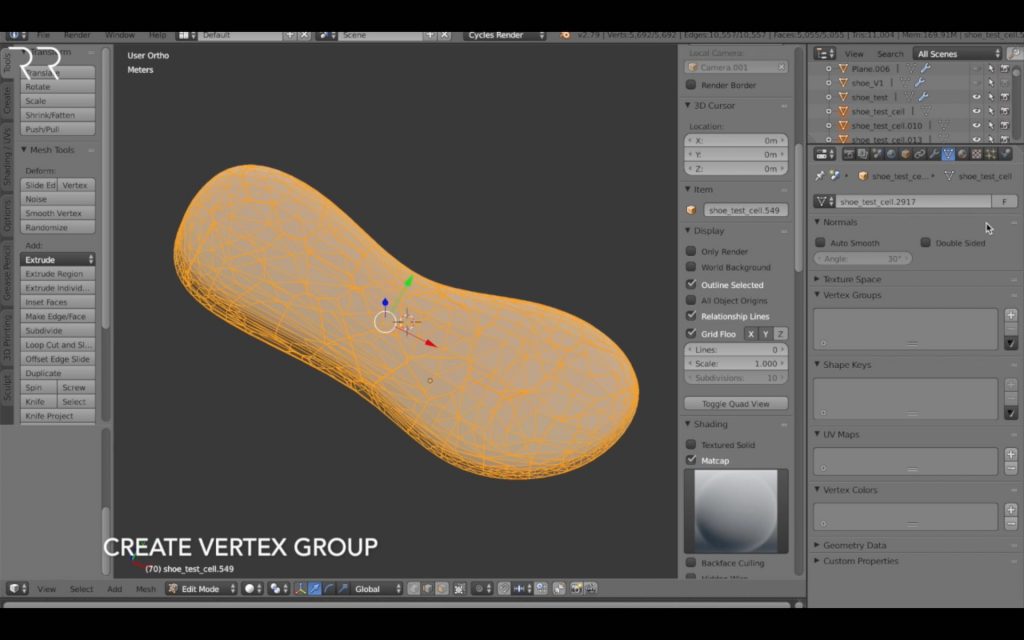
To apply different thicknesses to the lattice structure you have to create a Vertex Group which is influenced by the weight factor. I put the complete mesh in the group, since I am defining the strength via the weight paint. If you only would like to influence a certain area of ​​the mesh, without a thickness gradient, you would only put that area in the vertex group.

6. Color Paint the Lattice Thickness

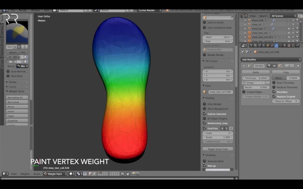
Using the Weight Paint mode and the tool Gradient Paint with Alt, you can create a color and therefore thickness gradient over the whole part. You can also freely paint areas with more thickness with red and the minimal thickness with dark blue. Afterwards select the vertex group in the wireframe modifier and you should see your painting represented in the thickness of your lattice structure.

7. Adapt Weight Factor and Lattice Thickness

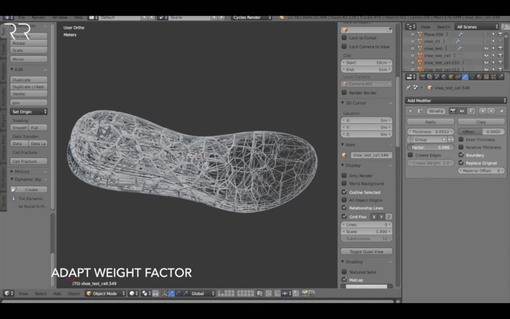
With the weight factor of your vertex group, you can control the strength or importance of your paintings. Factor „0“ means 100% importance and therefore zero thickness at the dark blue area. The red area has the same thickness as set at the wireframe modifier. Factor „100“ means the painting has zero importance and therefore the whole part has the thickness set in the modifier, no matter the painting.

You can play with the wireframe thickness, the weight factor of the lattice as well as the painting to create your ideal solution in terms of thickness. In the video I also used the Subdivision Modifier to create the smooth connections in the lattice structure. Keep in mind the minimal thickness of the additive manufacturing process you are using. Always adapt the design to the additive manufacturing technology and used material.

After applying the wireframe and subdivision modifier, I suggest you also use the Decimate Modifier to reduce the final file size of your STL file. The typical stl-size shouldn’t exceed 50Mb. Lattice structures with below 1mm thickness don’t need a lot of mesh resolution, since most additive manufacturing processes have a minimal resolution of 0.4mm.

I hope this quick overview on how to create 3D lattice structures is helpful for you. Please feel free to comment or send me your creations and ask me any questions!

Sign up to stay up to date about the newest tricks in

Design for Additive Manufacturing.

V

[ABTM id=2505]

Kommentare

2 Antworten zu „3D Lattice Structure Design for Additive Manufacturing“

  1. Hello, I was wondering if this method could be used to create a more uniform design for a 3D printed midsole, similar to what you have provided but with a more uniform pattern. Thanks in advance!

    1. Hello Will, thanks for the comment. A very good question. Making a uniform pattern of the vertices you can create a mor uniform lattice. However with this process it will be always a more or less random connection between vertices.
      To create uniform lattices you can use arrays and a boolean. Or check out my tutorial on 3D textures. You could use this approach to place lattice elements at certain points in a volume: https://www.romanreiner.com/complex-3d-textures-for-additive-manufacturing/

Schreibe einen Kommentar zu RomanReiner Antworten abbrechen

Deine E-Mail-Adresse wird nicht veröffentlicht. Erforderliche Felder sind mit * markiert

Diese Website verwendet Akismet, um Spam zu reduzieren. Erfahre mehr darüber, wie deine Kommentardaten verarbeitet werden.